Description of the Project:
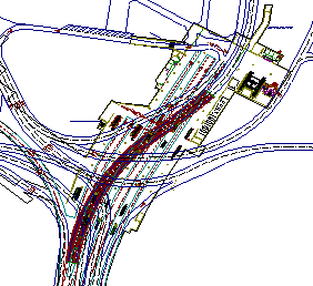
The project encompassed 5 junctions in Damascus metropolitan area. The existing capacity of these junctions was considered to be sub-standard due to the anticipated future traffic, which will render these structures insufficient to cater with the growing volume of traffic and the increased loading. Many structural deficiencies were detected in the bridges as well. Bridge/Underpass structures were required at some junctions or at stream crossing. These new designs should attain cost-effectiveness, structural efficiency, and aesthetics. See Appendix.
My Role in the Project (in Detail):
1) I reviewed the condition evaluation reports of the client for all these junctions.
2) I held the position of leading bridge group (4 engineers and 3 drafters) for the first stage of the project which was: to develop proposals of 10 new bridges and underpasses in 5 different junctions in Damascus metropolitan area. Till the day I moved to Canada, I submitted alternatives, comparisons and presentations to convince the client about the right solutions. The specific design requirements and details for each structure were supposed to be achieved during the detailed design stage, once the surveying, geotechnical and hydraulic studies had been completed. Of the wide variety of bridge configurations, the factors that favor the selection of some types than others in these proposals were: the relatively low cost of construction, the wide availability of concrete constituents, the good local experience in the construction method, the proven durability of properly designed concrete structures, the adaptability of concrete to large horizontal and vertical curvatures, and the social impact. In addition to the distinct torsional stiffness of the box form for the medium span bridges, and the freedom to form the edges, shadows, slenderness, rhythm and harmonies with the landscapes. These proposals were as follows:
· Shami Junction Bridges (3 bridges): The 1st bridge had 3 curved spans (30, 58, 30) prestressed box girder with inclined webs connected monolithically with the single column piers and the two integral abutments. The 2nd bridge had 3 curved spans (40, 51, 40) prestressed box girder with inclined webs. The structural system was the same as the 1st bridge except the pot bearing support on the spill-through abutments. The bridge superstructure for both bridges had solid diaphragms over the piers and abutments to control the overall torsional effects in the superstructure, fig. (24). The 3rd bridge had 3 skewed spans (22, 32, 22) prestressed voided slab section. It was frame with monolithic connection between piers with superstructure. The cylindrical voids inside the superstructure were less than 60% of the section depth; hence, the slab would behave isotropically. It was sculptured to match the best stress distribution in the optimized weight, as well as for aesthetic reasons. The piers were 4 tapered cylindrical columns. All these bridges were rested on pile foundations, fig. (25).
· The Main Corridor (U section and 2 underpasses): This underpass was a very important link in Damascus Downtown, as it connected the north and the south. It was under the ground level, with two different widths and transitions. It was basically a reinforced concrete U-shape structure, and all junction locations with this main corridor would turn to be at-grade overpasses. These overpasses had 2 different spans depending on the locations; it took the same shape of the U-shape structure but with a monolithic reinforced concrete slab forming box structure, see fig (26). The first type had about 20m span length, box shape structure, located at Thawra junction and Bab-Toma. The second type has about 27m span length, located at King Faisal Road. The top slab and walls thicknesses were tapered and determined depending on all loading combinations.
· The Thawra Bridge: The existing Bridge in its present condition was described as unpleasant and unable to complete the proposed 3 levels-separation junction. The proposal was indeterminate partially prestressed box girder bridge had 6 spans (basically it was 2 bridges 46, 60, 46 m) see fig. (27). I proposed 2 options for the superstructure; the 1st one was single deck box girder had the advantages of higher degree of redundancy, stiffer against applied loads especially lateral loads. It was also much pleasant, and had no sudden impact for the drivers. The 2nd one was two twin superstructures with cantilevers; it had advantages of simplicity of design and construction, and cheaper. The webs in both had ducts containing high yield pre-stressing cables. Once the concrete attains the design compressive strength, the cables will be tensioned and then grouted to ensure well bonded and long-term durability, see fig (28).
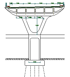
· The El-Jehad square Bridges (at grade slab, and a bridge): I paid special attention for this junction as it was 3 level separations, and had special conditions. In order to choose the best cheapest and the most pleasant bridge in this square, some special conditions precluded the use of some other types of bridges, these were: large train station under the square (underground), very busy square, the space that permitted to erect the piers are limited, the clear height of the piers around 23 m, besides the bridge located in 2 transitional curves, fig. (29). I proposed prestresed box girder superstructure, continuous into 5 spans (40, 52, 52, 52, and 40), and 6 simple supported approach spans 22 m. The approach spans were pretension cellular sections. The substructure had 2 closed abutments 4 hammer head piers that supported the approach spans, two rectangular hollow section piers that supported the end spans, and 4 primary piers that supported the main continuous superstructure. The primary piers had a shape like trees; see fig (30), each of them had 4 inclined legs rested on a rectangular hollow section. I assumed that the foundations of these main piers to be constructed on pile groups and some of them inclined 10º, fig. (31).
· Barada River Bridge: It was single portal, had the skewed angle of the river with the roadway.
3) Good understanding of the seismic load redistribution characteristics and the location of the vulnerable components were also needed for proper assumptions for those proposals. I used 3D FE spine (stick) models for those proposals to obtain: the general dimensions, the depths of the sections, as well as to find out the dynamic response characteristics for each proposed bridge, for instance: fundamental periods, mode shapes and the critical sections for the plastic hinges.
4) The proposals were developed to 30% complete stage and gained the admiration of the client.
5) The Bridge group in Halcrow proposed preliminary locations, length, heights and quantities for cantilevered reinforced concrete retaining walls, and I checked and revised them all as well.


Figure (24). Shami Junction bridges, a) second bridge, b) first bridge.

 Figure (25) Shami Junction third Bridge
 Figure (27) The longitudinal section of Thawra bridge


